My engine arrived this afternoon!
Over the past few years (as most of you know) I have been building up my 1987 IROC-Z camaro to be a street/strip/autoX/show car. I have upgraded the fuel system, installed a very beefed up 700R4 trans, 9" converter, a Moser 12 bolt rear, strong driveshaft, suspension components, bigger brakes, wheels, a wet nitrous system on the TPI setup, battery relocation, etc. Here is a link to the multi-year build up of the rest of the car itself:
http://www.njfboa.org/forums/showthread.php?t=68229 its 6 pages. lots of photos, info, and discussion.
It is finally time to bring in the engine, by which this new thread will be about....getting it installed, wired, plumbed, and setup. I have a pretty "ok" idea of what to do, but I also already have some questions and will need advice as I take on this task over the next few weeks. ANY/ALL advice (good or bad) is much appreciated. thanks
So the engine arrived today. It was built by Nyes Racing Engines out in Indiana.
Here are the basics, but I have attached a photo of the build sheet below:
- Dart SHP block
- 406 cubic inches
- Callies Compstar Crank and Rods
- Mahle pistons (rings are gapped for a 200-250 shot of nitrous)
- Dart Pro1 215 Cylinder Heads
- Comp Cams camshaft 245 intake/245 exhaust at .50, .4000 lift intake and exhaust, and 110 LSA (cam card below)
- Crane roller rockers
- Edelbrock Victor Jr manifold
- Holley Sniper EFI
- SFI 168 tooth flexplate
- MSD Pro billet distributor
Dyno Tested on February 2, 2020 (dyno printout attached)
Max HP was 531.6 @ 6,000 rpm
Max Torque was 513.0 @ 4,800 rpm
very happy with how it all went. I never wanted a super high horsepower high revving drag engine that was non-streetable. I always wanted a "hot-street" motor capable of doing "it all" well. street, strip, autoX, show, long cruises, etc. I'll take some time before getting the nitrous setup on it, but that is going to happen for sure
I plan on installing the engine in the car this saturday, and it will bolt to the new Prothane Polurethane engine mounts I installed. Today, I already mounted some of the front accessories (power steering pump, water pump, some pulleys) but I am still waiting on a mid-mount bracket set for the powermaster alternator. I also mounted the starter and did my best to check its alignment; see photo)
I have a champion 2 row (1" tubes) aluminum radiator on the way and will buy new hoses. A 160 degree thermostat was recommended by the engine builder, and I still need to buy a water neck. I will be re-using my OEM fans, but building my own relays to power them. The holley sniper unit will control fan 1 and 2 on/off. I will use evans waterless coolant also, and still have to find an expansion tank/overflow tank I can put neatly in the newly repainted engine bay.
- It took me a little while to understand the proper way to setup the fan relay diagram, but thanks to people on this board I think I have it worked out.
My biggest dilemma comes from some of the wiring that lies ahead.... I thought I had some of it figured out, but I seem to be getting into another confusing stage regarding the ignition wiring and some of the other topics below.....
Since I have removed ALL of the oem wiring that went to the TPI's ECM and its functions, I was left with wiring at the C100 connector, the C207, and the C221 along with the fuse panel, and in-car wiring. Things definitely cleaned up nicely under the hood and I wanted to do my best to keep it that way.
--I plan to use the Pink/black stripe wire coming from the fuse panels 10 amp ENGINE CNL port to trigger the sniper's ecm. (what does "CNL" mean anyways??) this pink/black wire used to go through port F of the C207 connector under the passenger dashboard but I removed it from the connector and plan on using it to connect to the new pink switched ignition +12v wire that leads to the sniper via it's built in connector? does this seem correct???
I thought that was the end of my ignition wiring questions, but sadly I realized when I did more reading that even though I own a MSD Digital 6 Cd ignition control box (currently removed and planned on selling it), I do NOT want to use it because on page 8&9 of the holley sniper quick start guide it states that "CD box ignition is intended for users that have an aftermarket ignition system but do not want the ECU to control timing". If I am reading that correctly, it means that the MSD digital 6 box would control timing, and would inhibit/prohibit the holley sniper from self-learning and self-tuning. ...
....thats not what I want. I want teh sniper to do the timing, tuning, everything. no external msd box is desired.
-- therefore, my only other option is for me to go buy a MSD remote mounted ignition coil (see page 8 of holley manual
https://documents.holley.com/199r11193.pdf). Since I do not have a large cap HEI .... I have a MSD pro-billet distributor #85551, I will NEED to have a remote ignition coil right??? something like:
https://www.summitracing.com/parts/msd-8202 or something different that works seamlessly with the MSD dizzy AND the holley sniper.. any suggestions? should I call holley tech on the phone and sort this out, or do you guys have any advice?
--after that dilemma, I then realized the issue might be even more complicated, since included with my Holley Sniper wiring harnesses, I located the "Holley Sniper EFI coil driver module".. which I had never heard of before today. this:
https://www.summitracing.com/parts/sne-556-150 . so now I am getting more confused about what I need to get the ignition system proper, and next, how to wire it. I will be searching online and on the holley forums, maybe even a phone call.. but if anyone can point me in the right direction, that would be fantastic. I am confused, very much so.
the second (but probably not the last) issue I would like to resolve, is what the best method for fuel pump wiring would be. I currently already have the Racetronix FL98 wiring/relay kit in the car
https://www.racetronix.biz/product.asp?ic=fpwh-005 and it is plugged into the oem bulkhead connector at the trunk area. So my plan was to keep this in place.... however the Holley sniper unit came with a pre-wired fuel pump relay and wiring!! so now I would have two relays for one 340 lph racetronix fuel pump. Initially myself and Polarbear decided that I should keep the racetronix relay and configuration, that would mean cutting up the brand new holley sniper wiring a bit, so before I do this, I wanted to see if anyone else had some thoughts or ideas?
- my gameplan would be, keep the racetronix wirign harness and relay in its entirety. I would then leave the OEM ground wire from the bulkhead to its chassis ground at the body under the rear seat. I would LEAVE the pink wire running along the drivers side rocker, since it goes to the dashboard fuel gauge, and I want that. I would keep the OEM tan wire along the rocker, but connect the sniper's "fuel pump trigger wire" to it, while then cutting out the sniper relay and its wiring?? if so, the schematic on page 14 of the quick start guide
https://documents.holley.com/199r11193.pdf does not show the trigger wire to the fuel pump relay... it only shows the blue wire which would run from the relay to the pump. I will check my actual wiring harness tomorrow, but I think the sniper's fuel pump trigger wire to the sniper relay is pink?? if so, I would just connect that to the oem tan trigger wire at the rocker panel??
I still have to figure out fuel line fittings too, thats up to me basically. I need some -6 fittings and a -8 to -6 reducer as well. I might add in some 90 deg or angled fittings to keep the fuel lines neat where the enter the holley sniper at teh back-side. I wish the handheld display for the sniper showed fuel pressure as a display, but it does not. I think I will (eventually) add in a mechanical fuel pressure gauge at the sniper so I can occasionally visually check the fuel pressure. my only question here is: would the mechanical pressure gauge go on the return line after the sniper's built in regulator ??correct??
for header gaskets: I have DynoDon's 1 3/4" headers and he recommended the Remflex RFL-2007 header gaskets. I trust him, but the shape of the ports doesn't seem to really match the actual ports on my Dart Pro1 215 heads. I bought the gaskets, but is there a better option?
is there a better solution to mount my oil-pressure sender unit? I removed the stock one from my 87 TPI engine, and cleaned it up. .. but it certainly will NOT fit standing up vertically (and looks goofy), and it will probably crush into the firewall if mounted with the 90degree fitting like oem style. Is there a less bulky, more compact, simpler oil pressure sender that I can put into the oil port on the top of the block (under the distributor by the intake) ? any other solutions or parts that would work? is there a different oil passage/port in a dart SHP block I could put the oil pressure sender unit into?? it would connect ONLY to my oil pressure dashboard gauge, via the tan wire that goes through the C100. ?? otehrwise, if I do need to keep the bulky sender, I will get a proper angled fitting like
https://www.ebay.com/i/153570139170?...RoC2LQQAvD_BwE
.. I am not really digging this orientation of the sender

last question for now:
pertaining to valve cover breathers... engine builder told me its a non-pcv system which I like. If I end up needing a catch can later, so be it, but I should be fine with the no-nitrous use N/A setup for a while. So I am going to order some push in breathers for the valve covers. my question is, can I orient the valve covers(and breathers) to both be at the rear of the engine? it cosmetically looks "goofy" to have one breather rearward and the other one towards the front on each side of the engine? There are no baffles inside the valve cover, so I think that any "pressure/breathing" would be fine if both breather holes are at the back towards the firewall. is this incorrect?

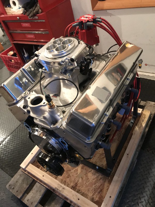
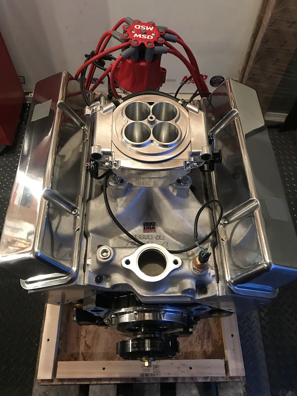
here are some photos.

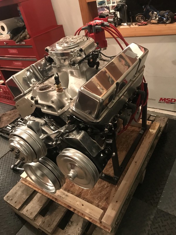
hows this for starter tooth engagement?


even more photos can be found at this photo album link which I will add to as I take more photos:
https://www.flickr.com/photos/iroczm...57713006026381
Sorry, a very long post. I hope to get some of this sorted out soon, and ANY advice is very much appreciated.