thanks. glad you guys mentioned the circuit breaker idea. once I did some research on it, I realized it was going to be much better than an ANL fuse since I would just have to re-click the circuit breaker if needed, instead of carrying around a pack of fuses and wrench to change them out (if ever needed).
- I wish I had got the adhesive lined shrink-wrap, with the glue like you mentioned. I have a cheaper brand that just shrinks. I've seen the glue lined stuff.. I think we used it in our 24 hours of lemons car.
sorry in advance for the long, detailed, update here....
I ordered the longacre kill switch, and it will be here on thursday. when I get it's front dress plate mounted, and gently carve out some of the plastic tail-light housing structure behind it, how am I going to get the four 1 gauge wires to the back of the switch.. I am pretty sure I'm going to have to cut some hole(s) in the car's sheet-metal, especially to fit the four large wires, that all have to come in at different angles, to sit on the 4 posts of the switch. I was wondering how people did theirs basically. I know the inner trunk plastic dress panel will cover any holes I have to make in the metal, but I was curious how others had routed their wiring from inside the car, to the back-side of the switch basically. somehow the 4 wires have to get through the sheetmetal behind the tail-light
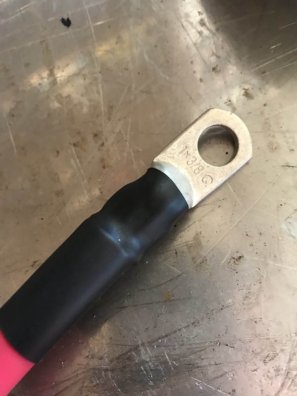
I brought all the mocked-up wiring over to Bruce's speed shop and used his hydraulic press back in the workshop area. that thing is cool and did a damn good job crimping on all of the 1 gauge terminals.... except the two terminals for the battery posts.. we soldered those ones together. photos below.
I then routed all of the wires in the car, labeled them accordingly, and mounted them in place with a combination of 1/2" clamps and zip-ties. Aside from the 4 wires that mount to the kill-switch, I have everything taken care of in the trunk area and the interior of the car.. up to where the wires will enter into the engine bay, by the firewall and lower foot panel on the passenger side
I wired the ground wire, alternator wire, and starter wires up momentarily in the engine bay. then I bolted the "companion connections" together where the kill switch will go, and then hooked up the battery. turned the car on, and let it run for a minute. was happy that it started and ran! I then unbolted one of the 2 "connections" that are where the kill switch will be (battery wire -> all engine bay wiring) and the engine instantly died. dome light an other electronics died also. Awesome. Next I tried the same with the other set of connections that will be at the kill switch (alternator-->circuit breaker-->battery). engine was running and immediately shut off when I undid the bolt. great! So, it seems like the wiring is correct and once the kill switch is in, it all should work properly. cool!
... question though, should the engine die when I click the circuit-breaker to trigger it "blowing"? I had the engine running and I hit he button to trigger the circuit breaker, but the engine did not turn off or do anything at all... should it have? or is the circuit breaker just there in case of a massive amp spike, yet will not impede current if I were to manually trip it?? is the circuit breaker "directional" and perhaps I have the feed in/out connections to it backwards? its in-line between the alternator wire and the kill switch wire, mounted in the trunk close to the battery box and kill switch area.. not underhood. you can see it in one of the photos below, should i flip it upside down in case it is directional??
I have a 4 post kill switch coming in the mail, not the 2 post style.
the longacre wiring schematic can be viewed here:
http://www.longacreracing.com/instru...nnect%20Switch
Positive wiring setup goes like this"
~ Battery top post ---> post A on kill switch ---> large junction post in engine bay --> one wire to starter and another to the future positive junction strip
~ 95/145 amp 1 wire alternator ---> 200 amp circuit breaker mounted in the trunk area ---> post B on kill switch ---> battery side terminal
Ground:
~ Battery top post ----> engine block ---> chassis ground (and soon will be grounding both cylinder heads together as well)
~ battery side post ---> chassis/frame ground at rear frame-rail of car
with the 4 post style kill switch, I thought this was the appropriate place to put the circuit breaker. I know the circuit breaker is not a kill switch, but I had figured that if I manually tripped it, the car would shut off. I guess not though .....
..... the reason I did not put any type of fuse or circuit breaker on the battery--> starter wire is because I read that the huge power surge that the starter needs to function would constantly trip the breaker/fuse. I had read that a circuit breaker should only be used in the alternator line in case of a problem power surge, the circuit breaker would trip.. and prevent harm to anything beyond the circuit breaker. is this correct? I am not a pro at this, so I am doing research and asking questions while trying to learn and understand as best as I can.
got the bulk of the interior back installed. once the kill-switch is here, i'll wire that up and take the car out for a short drive. after that, I'll be spending the rest of the winter working in the engine bay.. pulling out the old engine, redoing brake lines, eliminating proportioning valve, removing old radiator, removing old wiring and relays, welding up unused holes, primer, paint, and then installing the new engine.
some photos below of the progress... let me know if anything seems odd or wrong. thanks guys
the taylor box is bolted through the "floor" of the spare tire well, but it does not sit on the "floor". I built two aluminum side-shelves on each side of it, bolted the bottom of the box to these. next, I used the NHRA required 3/8" threaded rod to bolt the whole battery and box assembly to the "floor" of the spare tire unibody. I also cut some hollow aluminum tube to use as spacers between the bottom of the box and the foor.... to keep the box from deforming if I cranked too hard on the nuts at each end of the 3/8" rod. it may sound confusing, and I wish I took a photo of it, but it is damn solid.
Next, I am currently searching for a nice looking power distribution block to put up in the engine bay. I'll want to fuse this also. I am not sure if I want to/or need to use a ground wire junction block. I had planned on running the grounds in the engine bay over to a nice clean metal part of the chassis. should I use a distribution block?
here are some that I have in mind:
1.
https://www.google.com/shopping/prod...f90AR8Q8wIIhwM
2.
https://www.google.com/shopping/prod...DHQ4PBDzAgjzAg
3.
https://www.ebay.com/i/152141092075?...UaApOvEALw_wcB
4.
https://www.google.com/shopping/prod...f90AR8Q8wII6QI
thoughts? do I need a ground junction block? what size fuse should I put prior to the power distribution block so it doesn't get blown away if something goes awry when the starter is cranking?
Basically the Battery postive line will go to a positive jump-post in the engine bay. one wire will go directly to the starter. the other wire will go to a 150(??)amp in line circuit breaker, and then it will go to the power distribution block for all things engine and chassis that require a positive power lead.
I was thinking this for the distribution block because it has several large and several small screw terminals to use. thoughts?
https://12voltconnection.com/product...busbar-3-8-red
And for the circuit breaker (instead of an ANL fuse) I was thinking this:
https://www.summitracing.com/parts/s...iABEgKcxvD_BwE
__________________